1. Introduction
Automotive companies are in constant competition for technological advancement [1] . Companies such as Tesla, BMW, Audi, Waymo (Google), and others are currently experimenting with self-driving, or autonomous, vehicles. The question arises: Why is there a demand for autonomous vehicles?
According to a particular study, 94 percent of accidents are attributed to human errors [2] . These errors can largely be mitigated by removing human decision-making and entrusting it to computer-controlled vehicles. In the future, these autonomous vehicles are expected to be significantly safer than traditional vehicles with human drivers, primarily due to the rapid response capability of computers and their ability to communicate with each other. This technology has already prevented numerous collisions and will continue to improve in the future.
Autonomous vehicles can read lanes and stay within them. They can also recognize pedestrians, cyclists, and other motorists and take necessary actions to prevent accidents. Traffic issues, such as congestion, can be seamlessly resolved with this technology, as autonomous vehicles will be directly connected to each other. This will allow for higher speed limits on highways and more closely spaced vehicles, thus creating room for additional cars. In the future, even traffic signs may become obsolete as all necessary data can be stored in an online database accessible to all vehicles.
Furthermore, emissions from vehicles can be significantly reduced because autonomous vehicles can exhibit perfect driving behavior and always choose the most suitable routes. As this represents the future of our vehicles and is a topic of societal importance, we are conducting a mini-simulation of autonomous vehicles operating in a Smart City. In our mini-simulation, we will create our own autonomous vehicle equipped with sensors, which must navigate through intersections without collisions, while adhering to traffic lights and avoiding other vehicles.
2. Customer Requirements
Our task is to construct a self-driving vehicle capable of following a pre-determined route within a simulated city, comprised of 9 intersections arranged in a 3 x 3 grid. The vehicle will traverse such intersections 25 times on its route, consistently making the correct directional choices. It must also possess the capability to interpret traffic lights and stop lines. In the segments between intersections, the vehicle should maintain an acceptable speed by following a guidance line. Additionally, the vehicle must be able to detect preceding vehicles and avoid rear-end collisions or intersection collisions. Furthermore, the vehicle should include a graphical user interface offering visualization of essential information via wireless data transmission, enabling remote stopping or control of the vehicle. To accomplish all of these requirements, there is a maximum budget limit of 3500 units.
3. Design Choices and 3D Design
In this section, we discuss all the components required for our autonomous vehicle. These components were chosen in a way that ensured the design was feasible both practically and financially. Consideration was also given to the availability of components at the time of purchase and their compatibility with each other. The final design is illustrated with 3D drawings created in Solid Edge. The aim is to understand the spatial possibilities and anticipate potential issues. Aesthetic perfection is not the primary goal; rather, it is to outline the direction our design is taking.
The vehicle is controlled by a Raspberry Pi, as we have proficiency in Python programming. This choice significantly impacts other components because compatibility must be ensured. To begin with, all sensors must have digital outputs since the Raspberry Pi does not work with analog inputs. The sensors are mounted as shown in Figure 3, with the reflection sensor facing downward to recognize guidance lines and stop lines, the color sensor facing right to detect traffic lights, and the distance sensor at the front to detect preceding vehicles. The construction to connect all these components to the chassis consists of maker beams, bolts, and nuts. The sensors, as well as all other components, are mounted on the round chassis. This chassis is ideal because the rear wheels with a diameter of 42mm fit precisely, and maker beams can easily be attached. Smaller wheels have the advantage of reducing torque, resulting in higher speed. However, there is a possibility of slippage at lower torque, which is mitigated by using the appropriate motor, as we will discuss shortly. Smaller wheels were also used for the front wheels (diameter 32mm) to keep the front axle and the ground nearly parallel (even when the axle is turned), which is important for maintaining contact with all four wheels during turns. For this reason, the servo motor is not directly attached to the frame but is elevated using 90° angle brackets and maker beams (see Figure 3).
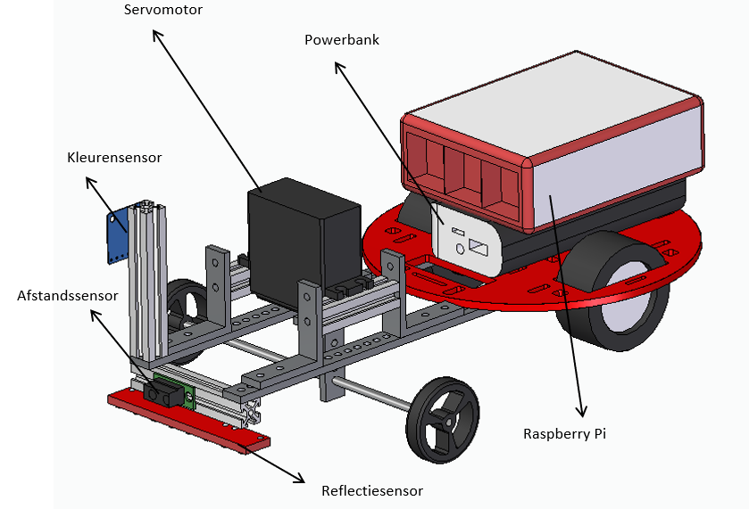
You might wonder why the sensors are positioned in front of the front wheels rather than behind them. The answer is quite simple: if it were the other way around, the sensors would only recognize a stop line or traffic light after the front wheels had already passed it. Additionally, the front wheel would obstruct the distance sensor. This problem was easily solved by constructing a frame with maker beams around the front wheels. To avoid slippage, the torque must be increased. Therefore, two DC motors with a 100:1 gearbox are used. These are attached to the underside of the chassis, leaving enough space at the top for other components (see Figure 3).
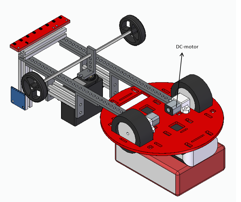
This slightly reduces the speed but is still sufficient to achieve the desired minimum speed of 1 meter per minute. For individual turning, we opted for a servo motor. In our design, the strong version is used because a significant portion of the vehicle’s weight rests on the front axle during turning. As seen in Figure [figure number], the front axle must be long enough so that the wheels do not touch the chassis and frame when turning. Hence, a 150mm axle is used, attached to the servo motor with an L-bracket. Additionally, a motor shield needs to be attached to the DC motors to prevent reverse voltage. The Raspberry Pi we use requires a 5V power supply, for which the power bank is perfect. However, the servo motor requires more power, so two 3.6V lithium batteries are also necessary. Finally, to connect all the electronics, a printed circuit board is mounted on the chassis using a maker beam.
4. Physical Design
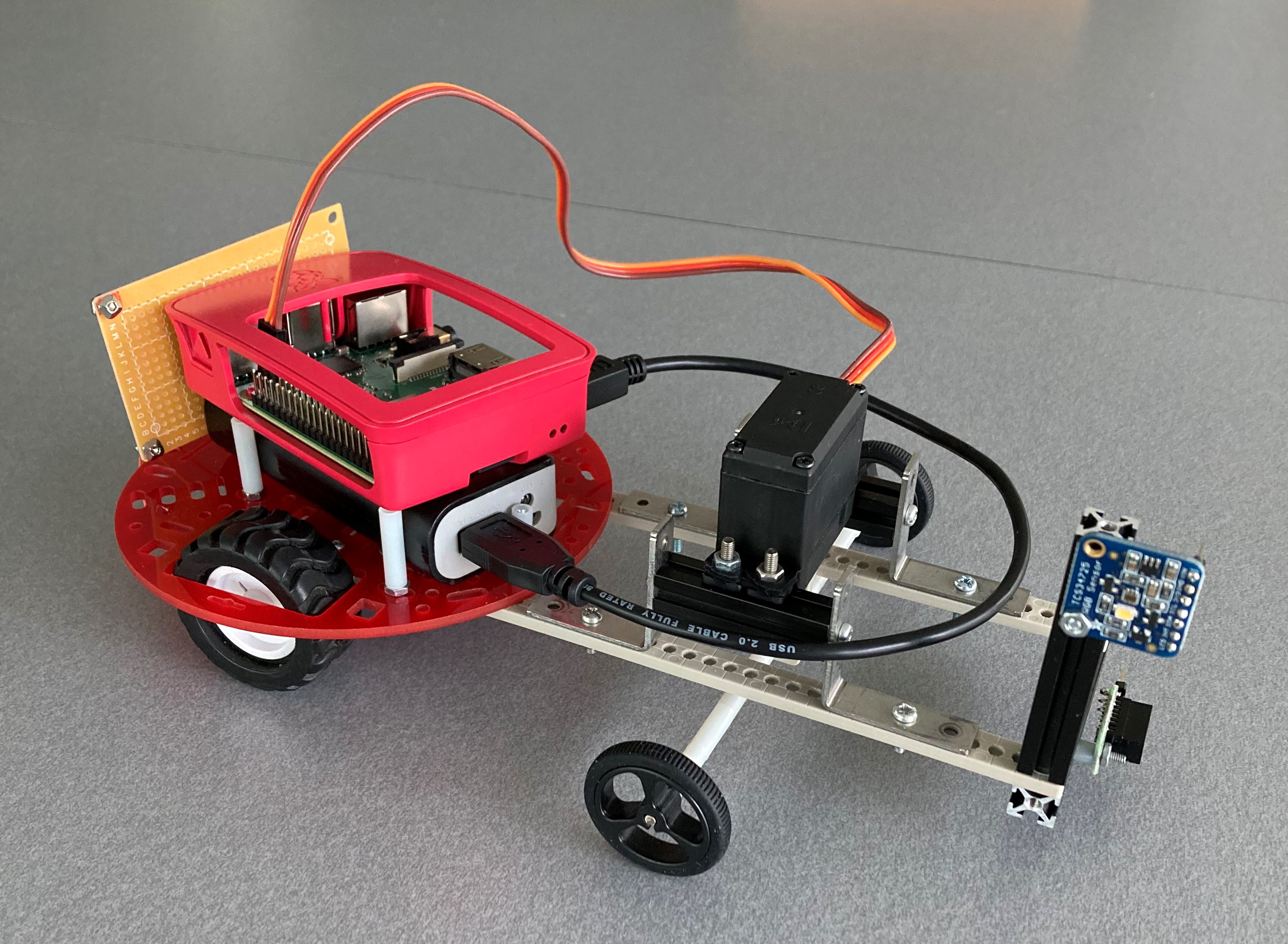
Following the design choices and using the CAD model as a reference, the physical design was assembled. In Figure [figure number], you can see the final result. Three minor adjustments are visible: nylon spacers have been added around the front axle to prevent lateral movement through the L-bracket. Additionally, the maker beam on which the reflection and distance sensors were mounted has been removed because the reflection sensor would otherwise be too close to the ground. This is not an issue for the distance sensor, which can be placed on the maker beam of the color sensor. Finally, the power bank with the Raspberry Pi on top is slightly tilted on the chassis to accommodate the printed circuit board behind it.
5. Technical Specifications and Electrical Circuit
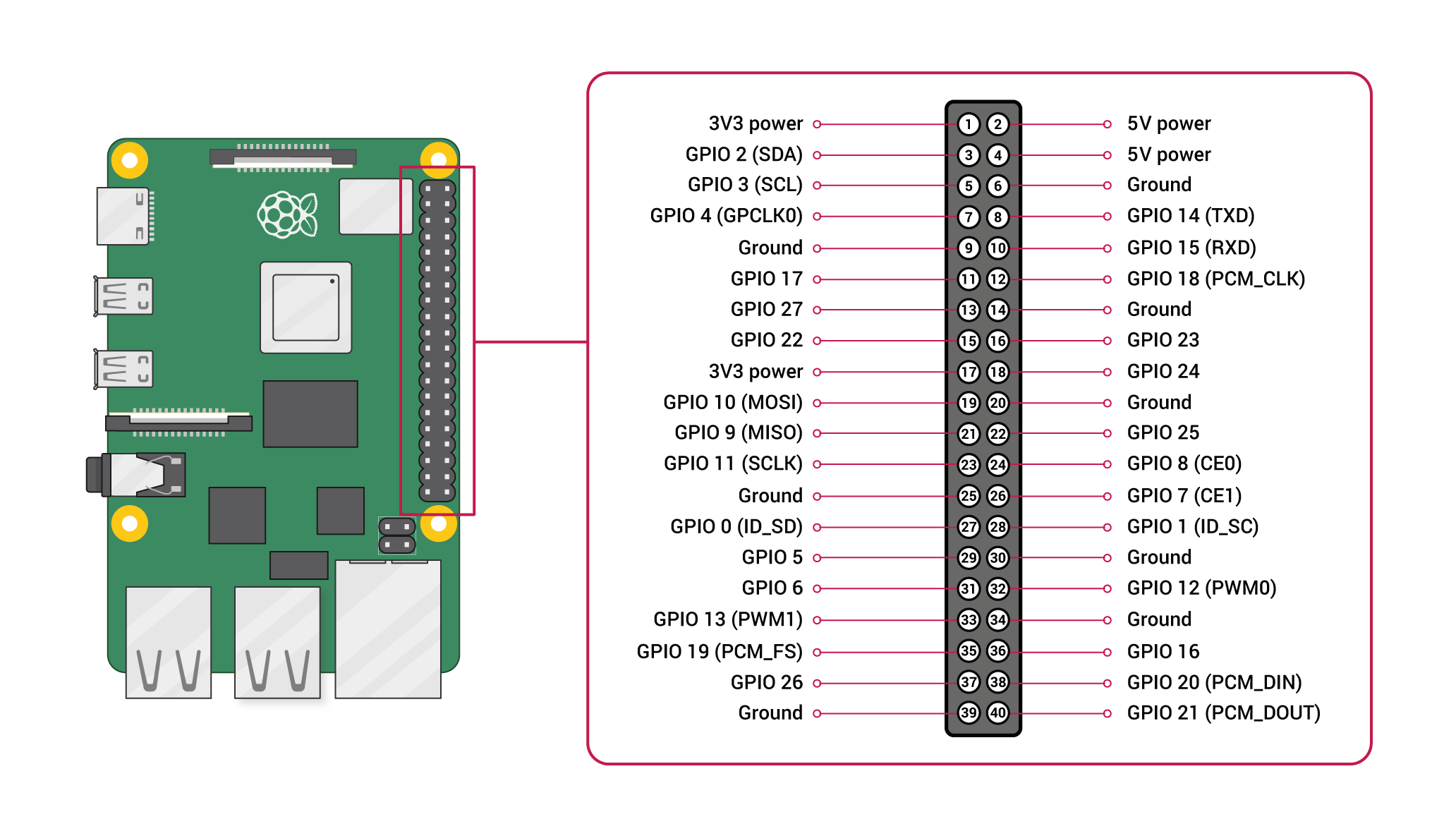
To begin, let’s explain the operation of the Raspberry Pi pins. The Raspberry Pi has 40 pins, numbered as shown in Figure 2. Each pin has a primary function, and some also have secondary functions. For example, Pin 1’s primary function is to provide 3.3V power, and it has no secondary function, while Pin 3 serves as a GPIO (general-purpose input/output) primary function and an SDA (serial data) secondary function. We decided to first connect the pins with secondary functions that are relevant to our project and then the pins without secondary functions that are easily replaceable. Finally, the remaining pins had secondary functions that were not important for our project.
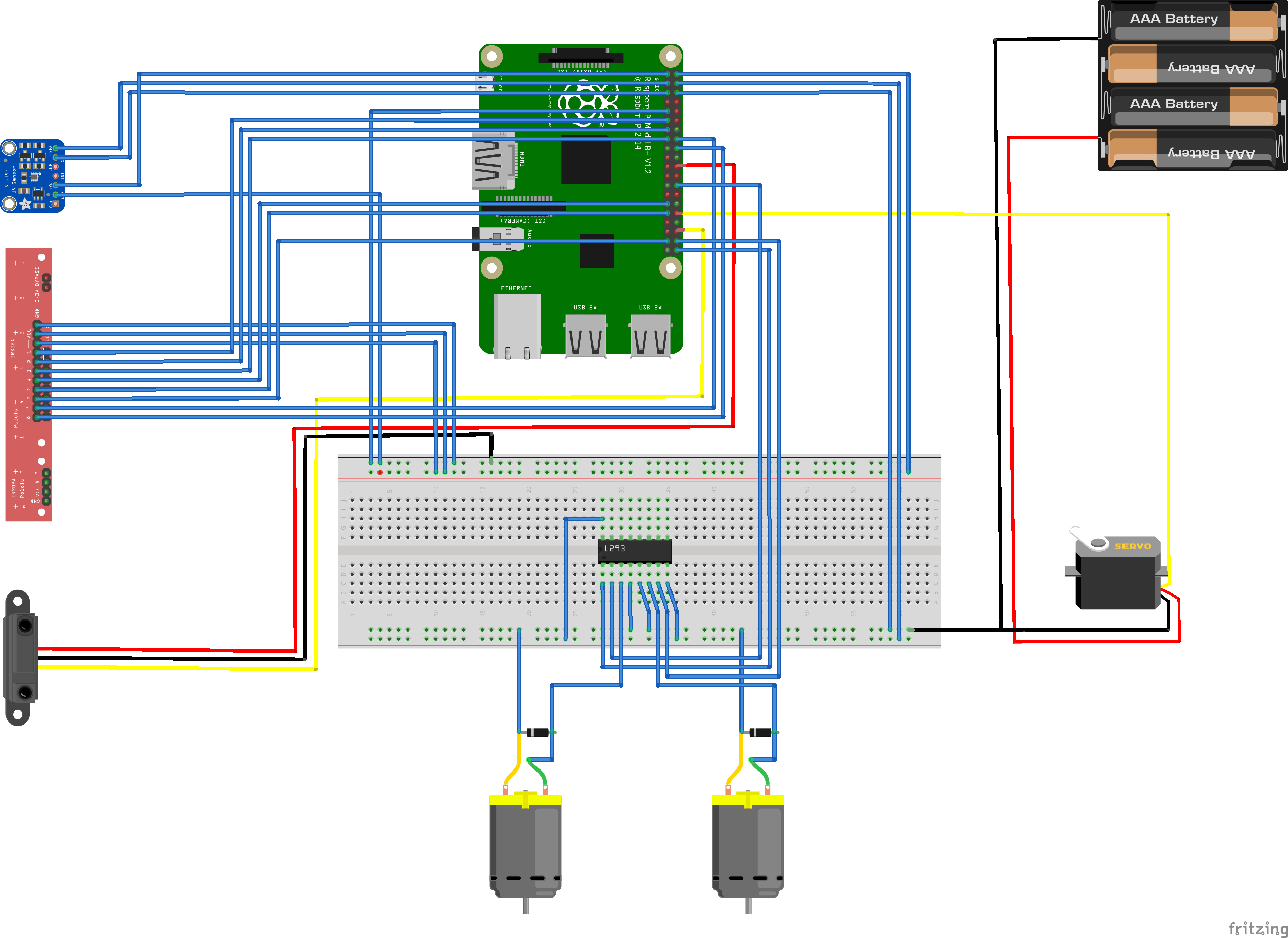
Figure 3 shows the result of all the connections. To clarify, here’s a brief overview of the most relevant connections. The color sensor requires two specific secondary functions, SDA and SCL (serial clock), which can be found on Pins 3 and 5. The color sensor also requires a 3.3V power supply (Pin 1). The reflection sensor has 8 infrared LEDs, so it needs 8 GPIOs without secondary functions (random GPIO pins without secondary functions as their primary function). The sensor also requires 5V power and 5V to operate the LEDs. The distance sensor needs one GPIO without a secondary function and a 3.3V power supply. The motor shield has a total of 16 pins, of which we will need one enable pin, two input pins, two output pins, and two power pins. The input and enable pins are connected to three GPIOs without secondary functions. The output pins are connected to the DC motors. Each power pin is supplied with 5 volts. The servo motor needs one GPIO pin with PWM (pulse width modulation) as a secondary function (to regulate voltages so that it’s not just 5V or 0V) and a 5V power supply.
6. Software
The implementation consists of three key parts. Firstly, we have individual Python subprograms responsible for reading sensors and controlling motors. These subprograms were later integrated into a main program (in Python), which also implements the entire navigation route for use during the demonstration. Finally, there is a manual control program in LabVIEW that is integrated into the main program. This LabVIEW control allows us to make an emergency stop or control the vehicle when issues arise. To facilitate collaboration, GitHub was used to share progress among team members.
The subprogram for the distance sensor is relatively simple. Since the sensor works with digital outputs, it registers either a zero or a one. A reading of one indicates that another vehicle is nearby, signaling the need to stop, while a zero allows the vehicle to continue moving.
The subprogram for the reflection sensor is somewhat more complex. It must read the guidance lines and the stop line (both are black on a white background). The sensor also operates with digital outputs and consists of eight separate smaller sensors arranged in a straight line (see Figure 3). If all eight sensors simultaneously detect a one (indicating they are over a black line), then the vehicle has clearly reached a stop line, and it should stop. To follow the line, a different approach is used. For instance, if only the two leftmost sensors detect a line, it means the vehicle is too far to the right. This information is communicated to the servo to correct the steering.
Similarly, if, for example, only sensors 6 and 7 (counting from right to left in Figure 3) register black, the vehicle is too far to the left, and it should turn to the right.
The DC motor control is relatively simple because we have chosen to use the servo motor for turning. Therefore, the DC motor only needs to drive at a constant speed, unless it needs to stop for a stop line or another vehicle.
The servo motor relies on the subprogram that reads the guidance line (these are very small corrections, at most a few degrees) and the pre-set route. When a right turn is needed at an intersection, the servo motor turns a certain number of degrees, and the same applies to a left turn. However, the servo motor does not work with degrees but with percentage rotation, so this needs to be converted using a small division function.
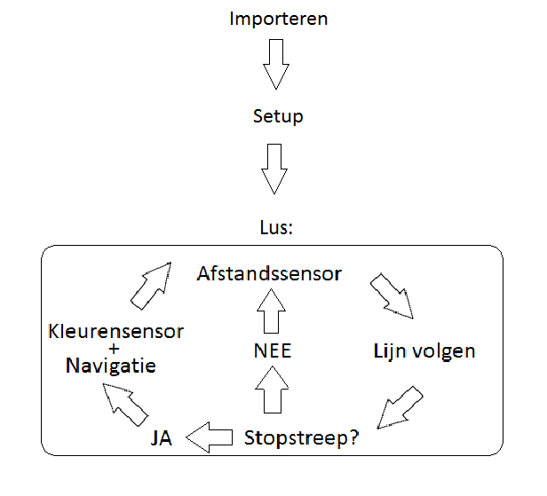
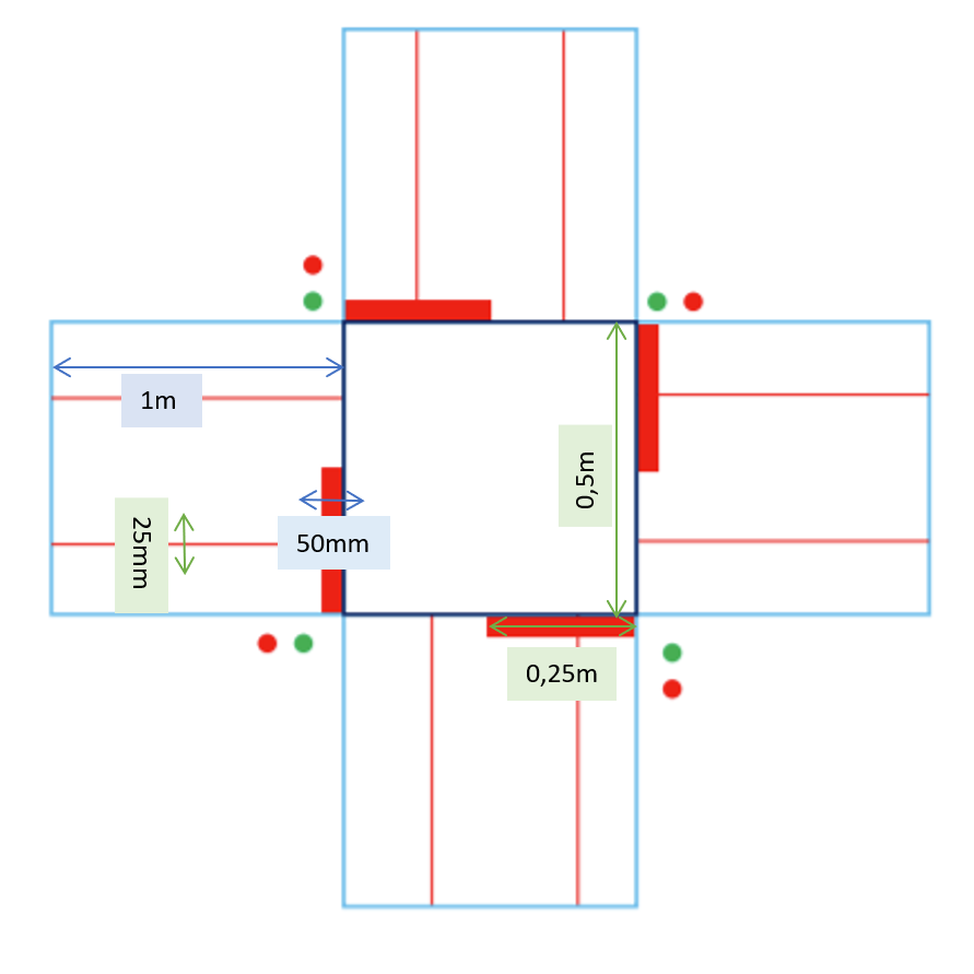
In the main program, these subprograms are combined to make the correct decisions. For example, if the reflection sensor detects a stop line, the color sensor reads the light. If it’s green, the vehicle proceeds in the desired direction; if it’s red, the vehicle waits. While driving, the distance sensor detects other vehicles, and so on. The route itself is implemented as an array, with each index representing a direction: 0 = straight, 1 = right, 2 = left (see Figure 4).
To control the vehicle remotely, as mentioned earlier, we use LabVIEW. The conceptual operation of the program is quite simple. LabVIEW receives input from the keyboard to which the program is connected. This input is converted into a string, which is then sent via a UDP connection to our main Python program. Based on this string, the main program decides what action to take. For example, if you press the right arrow key on the keyboard, it is encoded as ‘102’. Using the UDP connection, this is sent to the main program, which then decides, based on the transmitted string, what action to perform. In this case, ‘102’ will cause the servo to turn to the right using the appropriate subprogram.
7. Demo Test
Before the demo test, it was planned to run a test on the course. Some minor adjustments can be made during this testing phase. During the demo, each team had to showcase several aspects: “manual override,” “stop line recognition,” “line following,” “interpretation of traffic lights,” “taking turns,” and teams were allowed a maximum of two attempts to navigate the requested route with their vehicle.
During our first attempt, the manual override did not work, likely due to the poor connection between our laptop and the Raspberry Pi. However, the manual override worked during the second attempt. After the demo, several things became clearer. Our color sensor is programmed to work with color quantity and not with the raw sensor data. It is also not programmed to recognize the frequencies of traffic lights. The color sensor should have detected a blinking traffic light thanks to the frequencies present in the raw data. This would have allowed the robot vehicle to stop at red lights and continue at green lights. We did not address this aspect properly.
In some cases, the robot vehicle may fail to follow the next guidance line after crossing an intersection. The cause could be related to how the vehicle is positioned on the stop line. If the vehicle is positioned very far to the right or left on the stop line, it may have difficulty following the next guidance line.
Regarding manual override, our vehicle cannot reverse because we did not program it to do so, and changing the connections on the motor shield for this purpose would have been necessary. Due to limited power supply issues, this problem arose. While these power supply problems were resolved before the demo, the risk of altering connections and code again would have been too great. In such situations, someone would have to lift and move the vehicle.
8. Finances
For the entire project, we had a budget of 3500 virtual units. Since there was only a limited list of materials, we had to use these virtual units to bid for a spot to place orders. As a team, we decided not to bid too high strategically. We ended up finishing second to last in the bidding to ensure that we could make some crucial decisions. This strategy worked perfectly because we were able to order everything we needed, including the servo motor for our additional application. We also had a significant budget remaining to purchase various additional components. Looking back, we never had to worry about our budget throughout this entire project, as we still have 459 units left. What could have been improved financially was the more thoughtful ordering of our components. However, from the second reorder onwards, a penalty had to be paid. So, we ended up paying this penalty four times.
9. Reflection and Conclusion
Our robot vehicle works well except for the color sensor and reverse driving. Everyone who worked on the project made significant contributions.
References:
-
Dr. R.K.Garg. Business competitiveness: Strategies for automobile industry. Acta Applicandae Mathematicae, 2007-05-19.
-
Rasheed Hussain and Sherali Zeadally. Autonomous cars: Research results, issues, and future challenges. IEEE Communications Surveys Tutorials, 21(2):1275–1313, 2019.
-
raghavendrahassy. Exploreembedded-fritzing-parts-library. Link, laatste wijziging 14 Feb 2017.
-
vanepp Fritzing. Qtr 8 pololu line follower sensor part. Link, laatste wijziging 17 Aug 2017.
Authors: Rayan verheecke , Romeo Bostoen, Dries Debaes, Robbe Deproost, Pieter Mestdagh, Ibrahim El kaddouri